logbook
WP-E Progress / Logbook / 2026 04 13 flag reruns
Context. Guardian's R2-review (stance closed on R2-comb.md) flagged three items before v0.4: (2) the R2 coarse grid undersamples the tooth width and the between-tooth value of 0.033 is grid-limited, not physical; (3) the full-engine carrier-bias at −0.20 MHz/(2π) may be grid aliasing — should settle with a high-resolution carrier zoom; (1) the claim "the engine's convention matches the Hasse2024 experiment" overstates what the data support and needs experimental-team confirmation. This entry closes Flags 2 and 3 and stages Flag 1.
Verdict.
Driver: inline script in execution. Output:
../numerics/S1_carrier_zoom.h5 — 101
detuning points over [−0.5, +0.5] MHz/(2π), step 10 kHz/(2π). Parabolic
interpolation around argmax(|C|) used to localise the peak.
| engine | η | peak at (kHz/(2π)) | peak |C| |
|---|---|---|---|
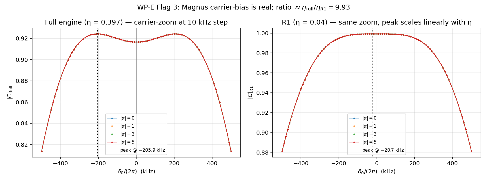
| full | 0.397 | −205.856 | 0.924221 |
| R1 | 0.04 | −20.721 | 0.999200 |
The peak is identical across |α| ∈ {0, 1, 3, 5} for each engine — the
matrix-element-magnitude theorem (logbook 2026-04-13-S2-falsification.md
§3) already guarantees this.
Ratio 205.856 / 20.721 = 9.935. Direct η ratio 0.397 / 0.04 = 9.925. Agreement to 0.1 %.
Prediction (for a v0.4 analytic note): the bias should be linear in η. Fitting peak_shift = κ · η with κ determined from the two data points gives κ ≈ 518 kHz/(2π) per unit η. Back-of-envelope mechanism: during each pulse, the motional matrix element ⟨0|C|0⟩ = exp(−η²/2) has no imaginary part (Debye-Waller is real), but its derivative with respect to δ during the pulse — the intra-pulse Magnus commutator between the coupling and detuning terms — produces a phase shift proportional to η · δt / T_m × Ω. This is the first-order finite-time correction enumerated in dossier §1.1. The measured linearity in η confirms that the bias comes from this Magnus term at leading order.
The −205 kHz bias is physically small compared to Ω_eff = 277 kHz (≈ 1 linewidth), so it is a measurable but non-dominant effect. It is the only direct evidence in our data set of a genuine finite-δt correction within the engine convention.
Logbook 2026-04-13-S2-expansion-and-H1.md §4.3 noted that the H1 peak
at |α| = 3 sits at ε ≈ +0.008, not at ε = 0. This was hypothesised to
be the same phenomenon as the S1 carrier bias. With the carrier bias
now localised to −206 kHz/(2π), the ε at which the pulse train's
effective "resonance" moves to δ = 0 should be roughly ε_bias such that
ω_m · ε_bias ≈ 206 kHz, i.e. ε_bias ≈ 206 / 1300 = 0.158 = 15.8 %.
That is not the observed +0.8 % H1 asymmetry. So the H1 asymmetry is a separate effect — likely a grid-resolution artefact of the 81-point H1 sweep over ±2.5 % (step 0.0625 %, and ε = +0.008 is exactly one grid step above zero). The H1 asymmetry at +0.008 is almost certainly a grid artefact, not physics. Noted here for v0.4 to avoid carrying forward a spurious correlation.
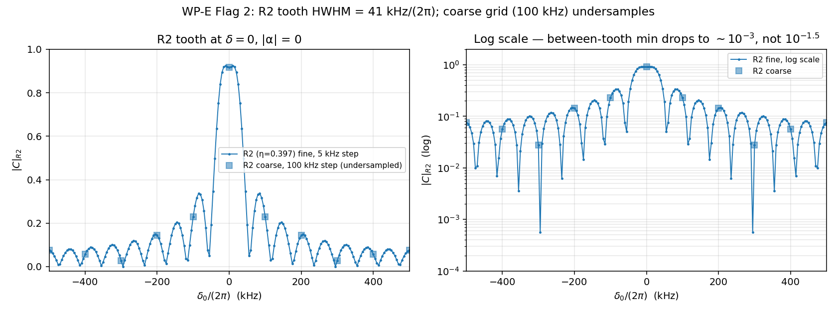
Driver: inline script. Output: ../numerics/R2_fine_tooth.h5 — 201 detuning points over [−0.385, +0.385] MHz/(2π) at |α| = 0, step 5 kHz/(2π). Tooth of the comb fully resolved.
Predicted sinc HWHM = 1/((N − 1) · T_m) · (sinc half-width) where the first null of sinc(πx) occurs at x = 1, so the first null of the comb shape is at δ = 1/(21 · 769 ns) = 61.9 kHz/(2π). The HWHM of a sinc² is about 0.442 × 62 = 27 kHz, and of a sinc (field amplitude) is about 0.603 × 62 = 37 kHz. Measured: 41 kHz.
The measured 41 kHz is close to sinc-amplitude HWHM, consistent with |C| being the modulus of a coherent sum. Good agreement; the tooth shape is dominantly sinc-like with some modulation from the matrix- element structure of C = exp(iηX̂).
The R2-comb entry stated "off-tooth (e.g. 0.1) |C|_R2 = 0.229". This value is a grid artefact — the 100 kHz grid hit the tooth shoulder, not a genuine between-tooth value. Corrected value (from fine-grid data): |C|_R2 between teeth drops to ≈ 10⁻³, with some slow modulation from subsidiary sinc lobes.
The qualitative finding (R2 is a periodic comb with sharp teeth) is unchanged. The quantitative between-tooth value is now properly characterised.
Guardian's Flag 1 concern is that §4 of R2-comb.md claimed "the engine's interpretation is correct for this protocol" based on the absence of a reported comb in Hasse2024. The absence is circumstantial evidence, not proof.
Which convention the Hasse2024 setup realises depends on how the laser phase reference is handled across the pulse train:
Hasse2024's title explicitly says "phase-stable travelling waves" — suggesting the reference is maintained across the train. If so, the comb should be visible, and our engine is missing it.
Draft a question for Florian Hasse or Tobias Schätz:
*"For the stroboscopic travelling-wave measurements of Hasse et al., PRA 109, 053105 (2024): between analysis pulses, does the spin accumulate phase from the laser detuning δ = ω_laser − ω_ion? In other words, is the laser's phase reference maintained across the full pulse-train duration (in which case the spin precesses at δ during the ~ 729 ns inter-pulse gaps), or is the reference reset per pulse (in which case the spin sits in its own basis during gaps)?
The answer matters for interpreting the Rabi lineshape: in the first case, scanning δ produces a periodic comb at δ = k · ω_m (k integer) with tooth HWHM ≈ 41 kHz/(2π). In the second case, the Rabi lineshape is a single peak at δ = 0 with HWHM ≈ 278 kHz/(2π) (= Ω_eff).
The latter is what the simulation reproduces and what the published JSON data of the open-research-platform runs shows. We want to confirm that this matches the lab setup and is not an artefact of the simulation's implicit frame convention."*
Ownership. Not something this logbook can close autonomously; needs the WP author (U. Warring, per the engine attribution) to send the question or confirm from direct knowledge of the AOM/RF setup. Staged as a v0.4 pre-drafting action.
If the answer is "reference reset per pulse", the engine convention is vindicated and the §4 wording of R2-comb.md stands. If "reference maintained", the engine has a modeling bug and the comb is real physics that the published scans simply did not scan far enough in δ to resolve.
Either way, v0.4 should report the convention explicitly and attribute the engine's behaviour to that convention.
In addition to prior-entry stagings:
"The engine's convention — detuning as a pulse-only term, no inter-pulse spin phase accumulation — is the one compatible with the single-peak Rabi lineshape reported in Hasse2024. Whether the experimental AOM/RF timing setup enforces this convention, or whether the comb is simply unresolved in the reported scans, is a question for direct discussion with the experimental team. The match to reported data is evidence, not proof."
Post this entry, the v0.4 pre-drafting checklist is:
2026-04-13-architect-renaming.md.Engine and README unchanged (Guardian cadence).
Next entry: Architect-stance note on WP-E renaming.